Start Isolation for Your ACR: Stop the Chartplotter and Stereo from Rebooting at Engine Start
If your plotter, radio or stereo reboots every time you turn the key even though you have two batteries and an automatic charging relay, the relay may be tying the house battery into the cranking dip. Learn how start isolation and dual-circuit battery switches keep the electronics on their own battery, how to find and test the start-only wire, and what to check after the job.
Time
2 h
Shop would charge
$150-600
Applies to
Outboard, Sterndrive (I/O), Gas inboard, Marine diesel
Safety first: The start-isolation wire connects to the starting circuit, the same circuit that makes the engine crank. Work with the battery switches off and the key out, except during the meter tests where a helper turns the key while you stay clear of belts, the flywheel and the propeller. Never bridge solenoid terminals with a screwdriver to "test" anything. On a gasoline boat, ventilate the engine compartment and run the blower first, and anything you add in that space must be ignition protected. If you see melted insulation or smell burning, switch everything off and call a marine electrician.
Owners often ask
- Why does my chartplotter reboot every time I start the engine even though I have two batteries and an ACR?
- Which wire do I connect the ACR start isolation terminal to?
- I have twin engines. How do I wire ACR start isolation so it works from either key?
This guide walks you through it. Still stuck? Ask the AI Mechanic about your engine.
Tools
- Digital multimeter (DC volts) with long test leads or a jumper lead
- A helper to turn the key
- Wiring diagram for your engine and boat (owner's manual, engine rigging manual or the builder)
- Wire stripper, ratcheting crimper and heat gun
- Flashlight or headlamp, phone camera and labels
Parts & supplies
- Small-gauge tinned marine wire for the start-isolation signal, in the size the relay's manual specifies
- In-line fuse holder and fuse for the signal wire, if the relay's manual calls for one
- Heat-shrink butt connectors or a proper tap connector, and heat-shrink tubing
- Optional - an ACR with a start isolation terminal, or a dual-circuit battery switch kit, only if your current relay lacks the feature
Before you start
Why it happens: when the starter turns the engine, it draws a big current and the voltage on the starting circuit dips (and can spike). On boats with an automatic charging relay (ACR, also sold as a battery combiner or voltage-sensitive relay), the two batteries are joined whenever the relay sees charging voltage. If the relay is still closed when you turn the key, for example right after a run, while a shore or solar charger is on, or because the house battery is sitting at a high surface charge, the house battery and everything on it share the dip. That is when the plotter, VHF, stereo or engine display reboot.
What start isolation does: some ACRs have a small extra terminal for a signal wire from the engine's start circuit. When that wire goes live, which happens only while the key is in START, the relay opens (or refuses to close) so the house battery is kept separate during cranking. Practical Boat Owner's owner-install of a small Blue Sea ACR describes it plainly: the optional start-isolation wire goes to the terminal that is live only when cranking, and it isolates the house loads from the engine's spikes and dips. After the engine starts, the relay goes back to normal automatic charging.
What this guide adds: our electronics power dropouts guide covers the basic voltage-sag checks (battery, terminals, grounds, wire size), and battery isolator types explains how ACRs compare with diodes and DC-to-DC chargers. This guide is about the start-isolation wiring itself and the battery-switch layout that goes with it. Do the battery and connection checks from the dropouts guide first: start isolation does not fix a weak battery or a corroded terminal.
Lithium house bank? An ACR is not the right charging device for most lithium house banks (Boating Magazine explains why); see our DC-to-DC charger guide. A DC-to-DC charger already keeps the banks separate, so start isolation is built in.
Steps
Write down exactly when the reset happens. It points to start isolation if:
- It happens only during cranking, not when the trim, windlass or bilge pump runs.
- It's worse right after a run or with a charger on (when the ACR is likely closed) than after the boat has sat overnight.
- Electronics on the house battery reset, even though you start on the start battery.
If the electronics are wired to the start battery or the engine side of the switch, start isolation won't help; they need to be moved (Step 7).
Why "right after a run" matters: Blue Sea's own explanation of ACR operation shows the relay does not open the instant the engine stops. Voltage has to fall a set amount below the combine point and stay there for a delay (about a minute in their example) before the batteries separate. A quick stop and restart, or a charger holding the voltage up, can leave the banks joined when you turn the key.
Find the ACR or combiner near the batteries or battery switch. Note the brand and model from the label and download its installation manual. Look for a small terminal or wire labeled something like "start isolation," "SI," "start" or "ignition," separate from the ground wire. Not every combiner has the feature; if yours doesn't, the fix is a relay that does, or a dual-circuit switch layout (Step 8).
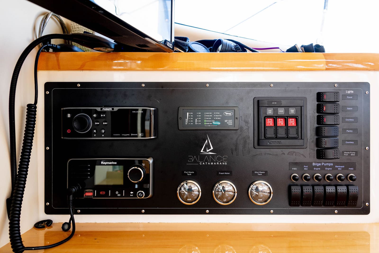
Stereo and VHF on the house side, with separate start and house battery switches: the layout start isolation is meant to protect. Photo: Craig Stanfill / Wikimedia Commons · CC BY-SA 2.0 Many boats have an ACR with the start-isolation terminal left empty, either because the installer skipped it or because it was "optional." Follow the small wire (if there is one) to see where it goes. If it's taped off, coiled up, or connected to an accessory or ignition wire, it isn't doing its job. An ignition or accessory feed is live the whole time the key is on, which is the wrong signal: the relay needs a wire that is live only while cranking.
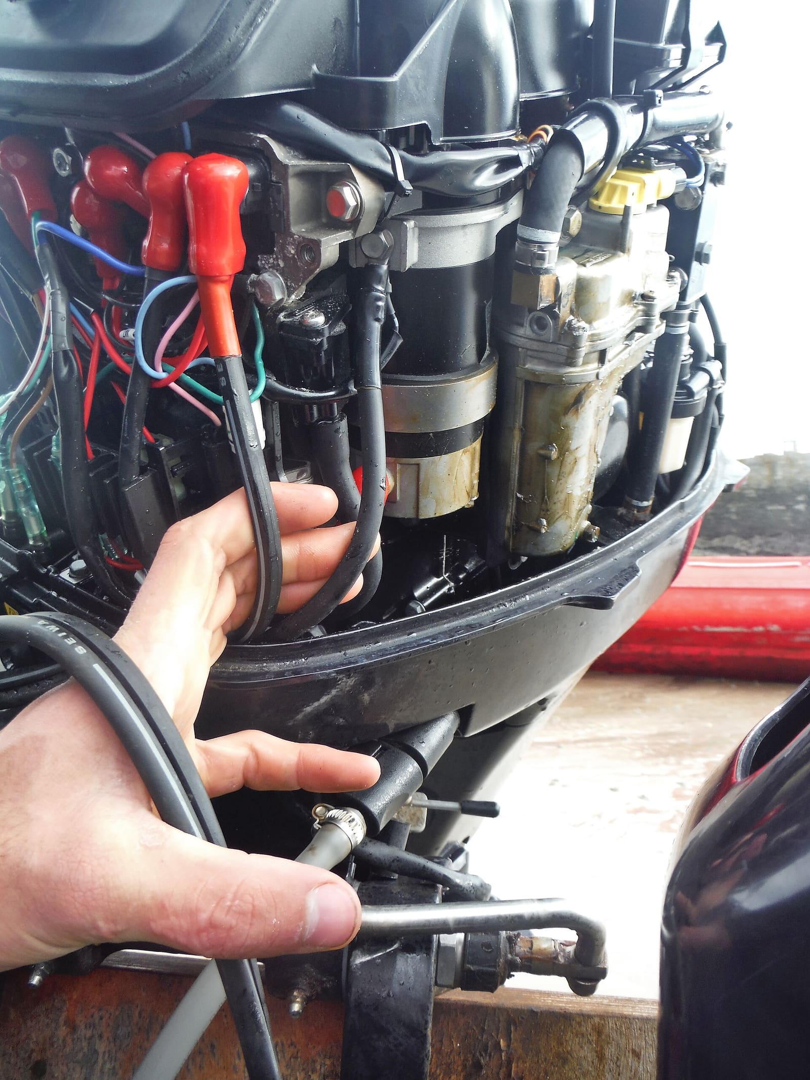
The signal you want is the wire from the key switch (or start button) to the starter solenoid, the "S" or "start" wire. Blue Sea's application note says exactly that: connect the start-isolation input to the starting circuit between the start key switch and the starter solenoid, so the same signal that engages the solenoid opens the relay just before the starter turns. ABYC's recommended color for that wire is yellow with a red stripe (NOAA's published wiring color chart lists the same), but builders and engine makers don't always follow it, and many modern engines run the key switch through a harness or a digital control module. Use the engine rigging manual or the builder's wiring diagram to find where that wire is reachable: behind the key switch, at a harness plug, or at the starter solenoid. Many owners find it hard to reach on outboards because the key-switch wires run in a harness straight to the engine; if you can't find an accessible point, that's a dealer or electrician job (see wiring diagram DIY for drawing your own map).
This is the step that prevents the most common mistake. With the battery switch on and a helper at the key:
- Set the meter to DC volts, black lead on a good negative.
- Probe the candidate wire (back-probe a connector or use a piercing probe only where your manual allows; seal any hole afterwards).
- Key OFF: it should read about zero.
- Key ON (RUN): it should still read about zero.
- Key to START: it should jump to battery voltage while cranking, and drop back to zero the moment the key returns to RUN.
If it shows voltage in RUN, it's an ignition wire, not the start wire. Keep looking. If your engine has a separate start button, test the button's output the same way. PBO's installer made a point of using the terminal that is live only when cranking.
With the batteries switched off:
- Run the signal wire from the start-only point to the relay's start-isolation terminal, in the wire size the relay's manual specifies, with a fuse near the tap if the manual calls for one.
- Use a heat-shrink butt splice or a proper marine tap; avoid household "vampire" taps that cut strands and corrode.
- Support and label the wire at both ends ("ACR start isolation") and keep it clear of hot or moving parts.
- Check the relay's ground wire too: Boating Magazine's install puts a fuse in the ACR ground lead, and a loose ground stops the relay from working at all.
Anything you add in a gasoline engine compartment must be ignition protected; see ignition-protected parts.
Start isolation only protects loads that are fed from the house side. Walk through the boat and note which battery each load uses:
- Electronics, stereo and VHF: house side.
- Engine, engine gauges and the engine's own electronics: start side (as the engine maker specifies).
- Bilge pumps and alarms: their own always-on fused circuit, never cut by a switch or relay.
PBO's installer found a cabin heater wired to the engine's supply; after the change it was running off the isolated start battery, so he moved it to the battery switch's accessory terminal. Look for surprises like that, and keep a list in your BoatMend log.
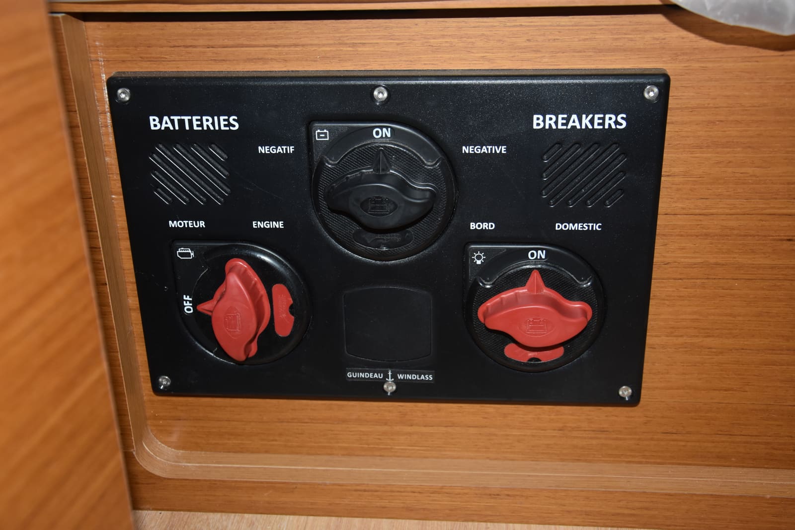
Many ACR kits come with a dual-circuit battery switch. Instead of a 1-2-BOTH selector, it has two separate circuits: the start battery feeds only the engine, and the house battery feeds only the house loads. Boating Magazine's ACR install wires the start battery to the switch's engine circuit and the house battery to the house circuit, and uses "combine" only when you need the house battery to start the engine in an emergency. With this layout plus start isolation, the house electronics never see the cranking current in normal use. Blue Sea also points out the protection works both ways: keeping the circuits apart stops house-side electrical noise from reaching the engine's electronic controls, and it lowers the chance of flattening both batteries at once.
If your boat has the older 1-2-BOTH switch, starting on BOTH ties everything together and defeats start isolation. See battery switches and dual batteries.
Switch the batteries on and turn the plotter and stereo on. Put the meter across the house battery. Have the helper crank the engine (outboards in the water or on external flush muffs, never dry; inboards in the water):
- The house voltage should barely move during cranking.
- The ACR's status light (if it has one) should show it open while cranking, then close again after its delay once the engine is charging.
- The electronics should stay on.
Repeat right after a run, when the relay would normally be closed. PBO's installer used his battery monitor to confirm that starting no longer affected the house bank. Write down the readings.
Know how to start from the house battery if the start battery dies: the switch's combine position, or the relay's manual override or remote button if it has one. Try it once at the dock so you aren't learning it at sea. Then return the switch to normal, because leaving it combined defeats both the isolation and the protection of the start battery.
If the electronics still reset with the relay proven open during cranking:
- The house battery itself is weak or deeply discharged. Load-test it.
- The electronics feed is undersized or has a bad connection or ground (see the dropouts guide).
- A device is actually fed from the start side.
- The device needs a steadier supply than any battery gives at a low state of charge. A DC-to-DC converter or stabilizer for that device is the next step.
Common mistakes
- Connecting the start-isolation wire to an ignition or accessory wire that is live whenever the key is on. The relay then stays open all the time and the house bank never charges from the engine.
- Tapping a wire because "it's yellow-red" without proving it with a meter.
- Leaving the battery switch on BOTH or COMBINE, which ties the banks together whatever the relay does.
- Forgetting loads that were fed from the engine side and now drain the start battery.
- Using a cheap tap connector that cuts the wire or corrodes, so the signal fails intermittently.
- Expecting start isolation to fix a tired battery or a bad ground.
- Adding a non-ignition-protected relay or connector inside a gasoline engine compartment.
When to call a pro
- The start wire is only reachable inside an engine harness, a digital throttle-and-shift system or a key-switch module
- Twin engines, where each start circuit has to be handled separately. Blue Sea's two-engine note uses a diode bridge so either key can trigger start isolation while the two start signals stay separate; never just join the two start wires together
- Replacing the ACR or battery switch, or moving loads between banks, if you aren't comfortable with heavy DC cables
- Any sign of heat, melted insulation or a burned smell at the switch, relay or solenoid
- Electronics that reset with the engine running, which points to the charging system (see charging system test)
Tips
- Until it's fixed, switch the plotter and stereo on after the engine is running and off before you shut down.
- Put a label on the relay saying where its start-isolation wire is tapped. The next technician will thank you.
- If your relay has a status LED, glance at it when you start: open while cranking, closed after a minute or two of running.
- On a new install, buy the ACR and the dual-circuit switch as a matched kit; the instructions then show exactly where the start-isolation wire goes.
Official references
We read these to write this guide. Your engine's own manual always wins.
- Practical Boat Owner – How to Install an Automatic Charging Relay on Board
- Boating Magazine – Automatic Charging Relay Installation
- Boating Magazine – The Basics of DC-to-DC Marine Battery Chargers
- Blue Sea Systems – Overcoming Dropout of House Electronics during Engine Starting
- Blue Sea Systems – Start Lockout for Two Engines
- Blue Sea Systems – ACR Operation
- Blue Sea Systems – Dual Circuit Battery Switch
Safety: BoatMend is for information only and does not replace a certified marine technician. You are responsible for your safety and your boat. Read the full disclaimer.
Last updated 2026-10-26
Related guides
Electronics That Reset or Shut Off When You Start the Engine: Finding and Fixing Voltage Sag
If your chartplotter, fishfinder, VHF or stereo blinks off or reboots when you crank the engine or switch on a big load, the cause is almost always low voltage reaching the device. This guide walks from the cheapest checks (battery, connections, grounds) to the real fixes: a dedicated electronics feed, start isolation between batteries, and voltage-stabilizing converters.
Battery Isolators Compared: Diode, ACR, Combiner and DC-DC Charger
Learn what the box between your engine and your batteries actually does, why an old diode isolator can leave batteries never quite full, and which charging setup suits an outboard, an inboard or a lithium house bank, plus a simple meter check of the one you have.
How to Use a 1-2-Both Battery Switch and Run Two Batteries
Learn what the 1, 2, Both and Off positions really do, a simple routine that keeps one battery ready to start the engine, how to check that both batteries are charging, and when an automatic charging relay makes life easier. Rewiring high-current cables is a job for a marine electrician.
Engine Clicks but Won't Crank - Testing the Battery, Cables, Neutral Switch, Solenoid and Starter
A click (or nothing) when you turn the key is usually a power delivery problem, not a dead engine. Work from the battery and cables through the neutral switch, start relay and solenoid to the starter motor using simple voltage-drop tests, and learn how to jump-start safely when gasoline vapor may be around.
Boat Ignition Key Switch: Diagnosing No-Crank and Intermittent Problems and Replacing It Right
A worn or corroded key switch can leave you with no crank, an engine that cuts out over bumps, or one that won't shut off. Learn how to rule out the battery, neutral switch and kill-switch lanyard first, test the switch with a meter, and replace it with the engine maker's switch wired exactly like the original.
12-Volt Boat Wiring Basics: Circuits, Color Codes, Fuses and Wire Size
Learn how your boat's 12-volt system is laid out, what the ABYC wire colors mean, how fuses and breakers protect the wiring, why voltage drop and tinned wire matter, and how to read a wiring diagram, so you can troubleshoot smarter and know which jobs belong to a marine electrician.
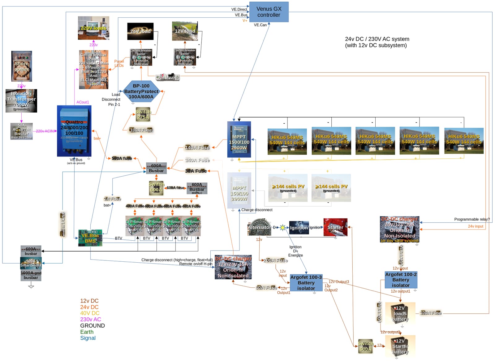
Make Your Own Boat Wiring Diagram
Trace your boat's 12-volt circuits one wire at a time, label them so the labels last, and draw a simple diagram you keep aboard. It takes a few weekends, but it turns every future electrical problem or upgrade into a faster, cheaper job.
Marine Battery Care: Test, Charge and Store for Winter
Check your boat battery's health, charge it the right way for its type (flooded, AGM or lithium), and store it so it is ready in spring. Most "boat won't start" calls start with a neglected battery.
NMEA 2000 Network Basics and Troubleshooting (Plus Chartplotter Updates)
Understand the backbone, terminators, power tap and drop cables that tie your chartplotter, engine data, GPS, depth and autopilot together, then track down why a device keeps dropping off. Finish by updating chartplotter and device software the safe way.